
When Maya Chen, a Cleveland maintenance supervisor, shut a quarter-turn valve for pump repair, a coworker turned its handle during shift change, and pressure spiked quickly. The valve was functional. The root cause lay in device selection and handover: a tag was fitted, but no physical handle restraint or clear ownership. The fix was proper lockout for this valve, stored energy control, and safe-position verification before work.
Summary: Fit a properly sized ball valve lockout over/through its quarter-turn handle, apply locks and tags, bleed residual pressure, and confirm the valve cannot shift. OSHA 29 CFR 1910.147 requires documented energy control, training and checks; tags alone are not physical barriers if lockout is available. Specify handle size, stroke, clearance, environment and group lockout needs before buying.
A Ball Valve Lockout holds the quarter-turn handle in a verified position
A ball valve uses a rotating ball to start or stop flow, so its handle normally travels about 90 degrees between open and closed. Lockout hardware must hold the designated safe position without blocking the bleed, gauge, or verification step. The device supports the procedure; it does not replace shutdown, isolation, stored-energy control, or a try step.
First notify affected employees and shut down the equipment under the written procedure. Close the correct valve, fit the Ball Valve Lockout to the handle, and attach a personal safety padlock and identification tag. The authorized employee should then release or restrain trapped pressure and verify isolation using the equipment-specific method before servicing begins.
Check the fit by trying the handle only after the area is safe and the procedure permits it. A device that slips, contacts adjacent pipework, or accepts no personal lock is not a usable control. Compare any candidate product by handle geometry and locking position before deployment.
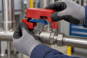
The device should prevent handle travel while leaving the verification point accessible.
A Ball Valve Lockout must fit the valve, handle, and work area
Record the handle thickness, width, operating angle, clearance around the stem, required open or closed position, temperature, chemicals, UV exposure, and number of workers. A device that fits a catalog photograph may still fail on a lever with a long stem, a restricted pipe rack, or a corrosive outdoor station.
| Control | Operating geometry | Main specification check | Procedure risk |
|---|---|---|---|
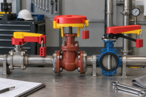
| Ball valve | Quarter-turn lever | Handle thickness, travel, and safe-position fit | Handle can be moved if the device slips or is undersized |
| gate valve lockout | Handwheel and rising or non-rising stem | Wheel diameter, stem clearance, enclosure size | Wrong cover may leave the wheel or stem accessible |
| butterfly valve lockout | Quarter-turn disc valve with narrow lever | Lever width, clamp range, and nearby clearance | Clamp may not capture the operating lever securely |
The table shows why valve name alone is not enough. The isolation point, safe position, and physical dimensions should appear in the equipment procedure and the purchasing specification.
A Ball Valve Lockout should be compared by application and total cost
The lowest unit price can become expensive when a crew must improvise, wait for a replacement, or repeat a verification after a poor fit. Consider compatibility, durability, inspection time, training, and the cost of an incorrect isolation as well as purchase price.
| Application | Priority | Useful checkpoint |
|---|---|---|
| Indoor process line | Correct travel and visible lock point | Confirm handle and pipe clearance during a trial fit |
| Outdoor or chemical area | Material and marking durability | Review temperature, chemical, moisture, and UV limits |
| Group maintenance | Individual control across workers and shifts | Use a hasp or lockbox so every exposed worker controls release |
| Contractor service | Ownership and handover clarity | Match lock numbers, tags, permits, and removal authority |
A Ball Valve Lockout supports compliance only inside a written energy-control program
OSHA 29 CFR 1910.147 covers servicing where unexpected energization, start-up, or stored-energy release could cause injury. It addresses procedures, employee training, periodic inspection, lockout and tagout devices, and verification. OSHA regulates the employer’s program; it does not blanket-certify every commercial valve device.
ANSI/ASSP Z244.1 is a consensus reference for hazardous-energy control and alternative methods, while ISO 45001 supports management-system discipline. Neither turns an unsuitable device into proof of isolation. CE or RoHS statements should be used only when supported and relevant to the destination market; they are not substitutes for a valve-specific energy-control procedure.
A Ball Valve Lockout purchase should begin with procedure fit
- Map the point: identify the valve, energy source, safe position, dimensions, and nearby hazards.
- Define verification: name the gauge, bleed point, visual check, or functional try that proves isolation.
- Test the hardware: confirm fit, lock access, tag visibility, and removal without unusual force.
- Plan people: set personal-lock, group-work, contractor, and shift-change rules.
- Control supply: keep the compatible-valve list, inspection record, and replacement trigger.
QD LOTO supports industrial buyers with configurable lockout/tagout hardware and sourcing documentation. Where several authorized workers share one isolation point, a multiple-lockout hasp can support the written group method; the final choice should follow the site’s risk assessment and procedure.
Frequently Asked Questions
How does a ball valve lockout work?
It physically blocks the quarter-turn handle in the required safe position so the valve cannot be casually reopened. The authorized employee adds a personal lock and tag, controls residual pressure, and verifies isolation before work. Select the device by handle geometry and clearance, not by valve name alone.
What is a gate valve lockout used for?
It encloses or restrains a gate-valve handwheel or stem so the valve cannot be operated during servicing. The device must match wheel size, stem arrangement, and the safe position named in the procedure. It is not interchangeable with a quarter-turn ball-valve device.
How do you install a gate valve lockout?
Shut down and isolate the line, place the correctly sized cover or restraint over the handwheel or stem, then attach the authorized employee’s lock and tag. Release stored pressure and verify that the valve cannot move before work starts. Follow the equipment-specific instructions and the employer’s written procedure.
Why do ball, gate, and butterfly valves require different lockout devices?
They use different operating geometries: ball and butterfly valves usually use quarter-turn levers, while gate valves use handwheels and stems. The lockout must capture the actual operating part, hold the safe position, and preserve clearance for verification. Using the wrong geometry can create a false sense of isolation.
References
- OSHA 29 CFR 1910.147, The control of hazardous energy
- OSHA Control of Hazardous Energy guidance
- eCFR Title 29 Section 1910.147
- CCOHS Lockout/Tagout guidance
The reliable sequence is simple: identify, isolate, lock, release stored energy, verify, and only then service. For a correctly specified Ball Valve Lockout, contact QD LOTO with valve type, handle dimensions, environment, and group-work requirements.