
Choose a butterfly valve lockout from the operating mechanism actually fitted to the valve. A squeeze-lever handle, a gearbox handwheel and a powered actuator present different locking interfaces. Identify the required safe position, measure the moving and fixed parts, and confirm an approved device configuration before ordering. A clamp that grips a handle is useful only if the complete arrangement prevents the prohibited operation; it does not establish that the line is depressurized or that the valve is leak-tight.
This guide addresses mechanism selection and sample acceptance for industrial buyers. It complements the broader valve lockout safety guide. Start with QVAND valve lockout options, then obtain instructions and suitability confirmation for the exact device and installed operator.
Classify the operator before choosing the lockout family
The word butterfly identifies the valve design, not the shape of the mechanism available for locking. On a manual lever assembly, the handle may have a release trigger and a notched position plate. On a gear-operated assembly, a handwheel drives a gearbox. A powered unit adds an actuator, its energy supply and possibly a manual override.
Record the valve identifier and operator model during a safe survey. Photograph the full assembly, the handle or wheel, and any existing locking features. Include nearby obstructions and the intended lock location. A close-up of a red lever alone may conceal the release mechanism that the proposed lockout needs to control.
Do not transfer the purchasing specification from a ball-valve lever or a gate-valve wheel merely because it looks similar. The acceptance question is whether the chosen configuration suits the actual interface and keeps the required position protected. Similar pipe sizes do not demonstrate similar lockout geometry.
For lever operators, inspect the release and travel path
Identify how the lever is released before rotation. Does a secondary handle lift, squeeze or disengage a catch? Where does the mechanism engage its position plate? The proposed device must be evaluated against the relevant movements rather than simply covering a convenient section of the lever.
Measure the handle width, thickness and profile where the clamp would engage. Note tapers, curved surfaces, coatings and any feature that could let the clamp slide toward a thinner section. Also record the clearance around the release trigger and the fixed reaction point, if the approved configuration requires one.
A clamp gripping the lever is not necessarily a complete motion restraint. Ask the supplier which components and configuration are required for that operator. A base clamp, blocking arm and cable attachment are distinct items in some product systems. Do not assume every photograph of the base unit depicts a complete installation for every valve.
For gear operators, assess the handwheel and gearbox separately
A gear-operated butterfly valve should not be treated as a long-lever application. Record the wheel diameter and depth, hub projection, spokes, gearbox housing and available installation space. Identify any purpose-designed locking feature described by the valve or operator manufacturer.
Where a wheel cover or another arrangement is considered, confirm that the selected model captures the relevant geometry and cannot be removed or defeated through the available access. Some enclosures restrict access to the wheel while rotating around it. Their intended protective function must be assessed under the instructions, rather than applying a universal rule that the cover itself must never move.
Also check for a manual override, an accessible shaft or another operating route. A wheel restraint should not conceal an unreviewed alternative way of moving the valve. Do not remove a handwheel, fit improvised wedges or modify the gearbox as a shortcut to obtaining a locking point.
Use a mechanism-specific selection table
This table is a qualitative inquiry aid, not a statement that a particular accessory is approved for all applications. The final configuration requires the equipment instructions, site procedure and a controlled sample assessment.
| Operator found | Details to collect | Acceptance question |
|---|---|---|
| Squeeze or latch lever | Lever profile, release movement, position plate and clearances | Does the approved arrangement control the movements that could change the valve position? |
| Gearbox handwheel | Wheel and hub envelope, housing, access and locking features | Does the device retain its intended protective function around the actual wheel assembly? |
| Powered actuator | Actuator type, supply isolation, stored energy and override provisions | Does the complete isolation plan address actuator energy as well as the process line? |
| Existing engineered lock point | Manufacturer instructions, hole dimensions and padlock clearance | Does locking that point actually retain the required state for this task? |
| Unclear or modified assembly | Current configuration, drawings and responsible engineering review | Can the interface and safe method be established before hardware is issued? |
Separate actuator energy from process isolation
A pneumatic or electric actuator can introduce motion hazards independent of the fluid inside the line. Depending on the design, springs, pressure or other stored energy may remain after a supply is disconnected. Identify these hazards and any approved restraint or release method before deciding that a locked operator is sufficient.
For covered US general-industry servicing, OSHA 29 CFR 1910.147 establishes the energy-control framework, including necessary isolation, stored-energy control and verification. It does not provide a universal valve-clamp installation or certify a particular accessory.
The existing compressed-air LOTO specification guide addresses residual-pressure and actuator questions in more detail. Use it to develop the energy inventory while keeping the operator-fit record specific to this valve.
A locked handle does not prove a sealed process boundary
Physical restraint of the operating mechanism and isolation of hazardous process material are separate matters. Internal leakage, connected branches, trapped pressure and the maintenance location all affect the process-isolation plan. A position indicator can help identify a state, but it is not a test of downstream pressure or seat leakage.
HSE HSG253, The safe isolation of plant and equipment, provides guidance on process-isolation planning and the prevention of releases during intrusive work. Its principles help explain why a purchased lockout device cannot determine the required isolation standard for every fluid, pressure or intervention.
Have competent personnel specify the necessary line controls and verification. Do not prescribe a single locked butterfly valve as adequate for all line-opening work. The lockout selection should support the approved boundary without obscuring any gauge, drain, vent or other feature needed by that plan.
Trial the exact configuration on a safe representative interface
Obtain a sample with the components intended for the order and compare it with the recorded operator geometry. Use equipment placed in a safe condition through authorized procedures, or a suitable de-energized mock-up. Do not manipulate a live process valve merely to demonstrate that the clamp fits.
Follow the specified assembly method and check engagement, retention and padlock clearance. Use the actual padlock family, not a thin substitute that makes the sample appear easier to close. Confirm the permitted movement checks without applying an invented force, and record any gap, interference or uncertain engagement.
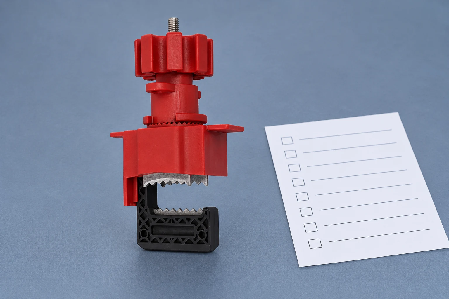
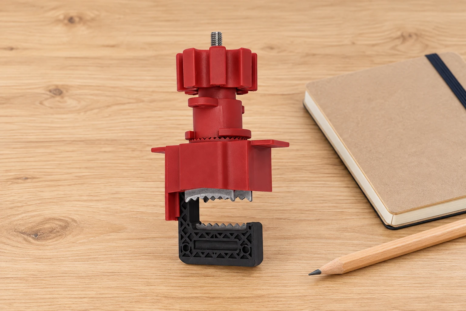
The QVAND butterfly-valve base clamp is the real product reference for this article’s illustrations. The generated backgrounds retain its photographed screw, knob, serrated jaws and body. The images show an uninstalled sample; they do not claim that this base unit alone fits every lever or gearbox.
Plan personal-lock access and shared work
Check the space required by the complete locking arrangement and identification tag. Access that is adequate for one small lock may not accommodate the planned combination. If a hasp or group arrangement is needed, confirm that it is permitted and that the locking interface remains effective with the additional hardware.
Keep the number of workers separate from the number of isolation points. The article on planning hasps for multiple energy sources explains that distinction. A multi-hole accessory does not automatically secure another valve or actuator supply elsewhere in the system.
Identify responsibility for joining, leaving and restoring the job. Where several tasks share the valve boundary, finishing one task does not automatically authorize reopening it. Record dependencies before the maintenance window rather than discovering them when a worker wants to remove a lock.
Specify rejection criteria and retain the accepted sample record
Reject an arrangement that slides off, leaves the relevant release accessible contrary to its intended function, fails to engage fully or requires unapproved modification. For the hardware itself, use the manufacturer’s inspection criteria for damaged threads, distorted jaws, cracked bodies and unreliable closure. Remove questionable items through the site’s process.
Retain the device model, complete component list, padlock combination, interface photographs and approval scope. A valve repair can change the lever, wheel or position mechanism without changing the pipe designation. Recheck the application when the equipment or issued hardware changes.
The CCOHS lockout overview connects device selection with responsibilities, training and documented procedures. Read its Canadian guidance in context and apply the rules relevant to the actual site.
Send a complete butterfly-valve inquiry
Provide the valve and operator identifiers, required safe position, mechanism type, measured interface dimensions, available clearance and intended padlocks. Include the environment and the full list of components to be supplied. Ask the supplier to identify any assumptions or unresolved fit details before quoting a batch.
Request instructions for the exact model and a sample-acceptance plan. Keep supplier confirmation of product characteristics distinct from site approval of the energy-control procedure. This makes the order easier to inspect and helps prevent a universal-product name from becoming an unsupported application claim.
Watch: place device selection within the lockout sequence
Workplace Safety & Prevention Services explains hazardous energy and the overall lockout process in this educational video. It reinforces the distinction between selecting hardware and verifying protection; it is not an installation tutorial for the pictured clamp.

Watch the WSPS lockout education video on YouTube.
Frequently asked questions
Can a lever lockout be used on a gear-operated butterfly valve?
Do not assume compatibility. A gearbox handwheel has a different interface and needs its own approved arrangement, measurements and sample assessment.
Is gripping the butterfly-valve lever enough?
Not necessarily. The full configuration must perform its intended restraint, including control of relevant release and operating movements. Confirm any required accessories and instructions.
Does locking the operator establish leak-tight isolation?
No. Process isolation, residual energy and verification must be addressed separately for the actual maintenance task and fluid hazards.
Which photos should accompany a quotation request?
Include the complete operator, release mechanism or wheel, fixed features, clearances and intended locking location, identified to the valve and required safe position.
Review the referenced QVAND product and send your application details for a model-specific sample discussion.