
A rising-stem gate valve lockout must fit the handwheel, the stem position and the space needed to install and secure the device. Handwheel diameter alone is not enough. Measure the valve in the safe position specified for the task, confirm the lockout’s approved stem-clearance arrangement and trial the complete device with the intended padlock. Never cut a new opening or force a cover closed to make an unsuitable model fit.
This guide focuses on rising stem gate valve lockout measurement and acceptance. It complements the site’s gate-valve application guide by examining the clearance problem in more detail. Use the QVAND valve-lockout range to identify candidate hardware, then obtain exact-model instructions and confirmation for the actual valve.
Distinguish valve geometry from isolation performance
A rising stem changes its exposed position as the valve operates. The stem can project through or beyond the handwheel region, creating an obstruction that a simple diameter measurement misses. Inspect the actual valve design: wheel, spokes, hub, stem, yoke, fittings and surrounding structure all affect access.
The required safe position comes from the isolation plan, not from a product photograph. A cover suitable for one stem position may not seat at another. Do not move an operating valve just to find the position that best fits a sample lockout. Arrange measurements under safe, authorized conditions, using manufacturer drawings or an appropriate mock-up where necessary.
Also separate a fit decision from a process-isolation decision. A device can restrict access to the handwheel while fluid hazards remain downstream or another route remains connected. The safe intervention depends on the defined isolation arrangement, residual-energy controls and verification, as well as the mechanical fit.
Measure five parts of the available space
Begin with the wheel’s maximum outside diameter, including any feature projecting beyond the nominal rim. Then record wheel thickness and the axial space occupied by the hub. A wheel with a deep hub may require more internal cover depth than another wheel with the same diameter.
Next, record the stem’s diameter and projection at the specified position. Identify where an approved opening would pass around it, whether the parts can be positioned without contact and whether the yoke prevents assembly. Do not assume that every circular cover has an opening for a stem.
Finally, measure access around the wheel. Nearby pipework, insulation, a wall, a chain operator or a support can prevent the halves from being placed or the closure from being reached. Include the space occupied by the applied padlock and tag, not just the empty cover. Photograph the front and side from a safe location and link those photographs to a valve identifier.
Use a clearance record rather than a diameter-only order
The following is a practical purchasing record. It deliberately contains no generic safe clearances or manufacturer dimensions. Obtain the candidate model’s internal dimensions and installation instructions, then compare them with the measured valve and the intended operating position.
| Measurement or condition | Record from the valve | Confirm for the lockout |
|---|---|---|
| Handwheel envelope | Largest outside diameter, rim thickness and hub projection | Internal space and supported wheel geometry |
| Stem | Diameter, exposed projection and required safe position | Approved clearance or opening arrangement for that model |
| Assembly access | Space around the wheel, yoke and adjacent structures | Path needed to place, close and remove the device safely |
| Lock and tag | Actual padlock shackle, body and identification needs | Closure remains secured and accessible with the full assembly |
| Process access | Nearby indication, drain, vent or other procedure-defined features | Installation does not obstruct required verification or monitoring |
| Environment | Expected temperature, moisture, chemicals and exposure duration | Documented suitability of the exact supplied configuration |
Mark an unknown field as unresolved rather than entering zero. For example, an unavailable stem-projection dimension is not the same as no stem projection. A purchasing record should reveal what still needs confirmation before sample approval.
Do not create a stem opening without explicit instructions
Some lockout designs have a manufacturer-defined provision for particular stem arrangements. Others do not. A feature on a different supplier’s product, a different size in the same range or an older instruction sheet cannot authorize modifying the chosen device.
Ask for the exact model’s permitted configuration. If the instructions describe an intended removable section or another adjustment, confirm that it applies to the supplied version and follow the specified method. If there is no such provision, do not drill, trim, split, heat or bend the cover to gain clearance.
An improvised opening can change retention, make the cover easier to remove or weaken a closure. Even a neatly finished modification needs explicit approval rather than a visual judgment that it “looks strong enough.” Where the model cannot fit as supplied or through its approved adjustment, reject it for that application and assess suitable alternative hardware.
Assess the installed arrangement, not whether the wheel can be seen
With the valve in the specified safe position and the assessment performed under authorized safe conditions, assemble the device exactly as instructed. Check that both parts seat correctly, the closure engages and the intended padlock actually prevents release. A lid resting against the stem can appear closed without reaching its designed locking position.
Check whether the secured device can be lifted away or displaced enough to defeat the intended restraint. Use the manufacturer-defined checks and the site’s acceptance method; do not apply an invented force or risk moving a live process valve. Some enclosure designs may rotate freely around a captured wheel while restricting access. The acceptance criterion is their intended protective function, not a blanket requirement that every external surface be immobile.
Record the accepted configuration with photographs showing the wheel, stem, cover position and lock interface. If visibility is limited, record the limitation and obtain the evidence needed to resolve it. Never declare success simply because the padlock clicked shut.
Keep clearance checks separate from leak-tightness checks
A retained handwheel does not establish that the valve seat prevents flow or that a downstream line is depressurized. Internal leakage, trapped material and connected routes require separate consideration in the process-isolation plan. Do not treat the visible stem position as a pressure measurement.
HSE HSG253, The safe isolation of plant and equipment, discusses isolation planning for process industries and intrusive work, including the role of draining and venting. It is broader process-isolation guidance, not a certification of a particular cover or an instruction that one locked valve is sufficient for every intervention.
For covered US general-industry work, OSHA 29 CFR 1910.147 requires the applicable energy-control sequence and verification before servicing. The hardware’s fit supports that sequence. It does not determine the necessary isolation standard for a particular hazardous fluid or task.
Review access for verification, identification and people
Consider what a worker must see or reach after the cover is installed. A tag needs to identify the relevant control without obscuring necessary information. Gauges, drains, vents and other procedure-defined features must remain accessible where the plan requires them. Do not route a lock or tag across a feature needed for safe verification.
For multiple workers, check the actual approved locking arrangement. The padlock holes and the available physical space both affect usability. A hasp may be appropriate where the model and procedure permit it, but do not hang additional devices from a cover without confirming the complete interface.
The complementary safety lockout hasp guide explains personal-lock attachment. For an irregular geometry where another method is being considered, the cable routing and slack checklist provides a separate acceptance framework. A cable is not an automatic solution whenever a cover fails a fit check.
Handle heat, insulation and weather as model-specific conditions
Measure the configuration as it will actually be encountered. Insulation added around a line, a protective stem guard or a changed support can reduce the usable space. Record those features rather than assuming a bare-valve drawing describes the installation.
Obtain documented environmental limitations for the exact cover, closure and any other components. A red plastic body does not reveal a temperature rating, and a metal part does not by itself establish resistance to the site’s chemicals. Do not transfer specifications across the entire category from one model.
Plan inspections for damage, distortion, degraded labels and closure problems. Remove questionable hardware through the site’s process and reassess after valve repair or replacement. A different handwheel or rising-stem arrangement can invalidate an earlier fit approval even if the nominal pipe size stays the same.
Send a complete rising-stem application package
A useful inquiry includes the valve identifier and design, required safe position, wheel diameter and thickness, hub detail, stem diameter and projection, surrounding clearance and proposed padlock. Attach photographs from more than one angle and state the environmental conditions. Ask the supplier to flag every unresolved dimension or intended-use limitation.
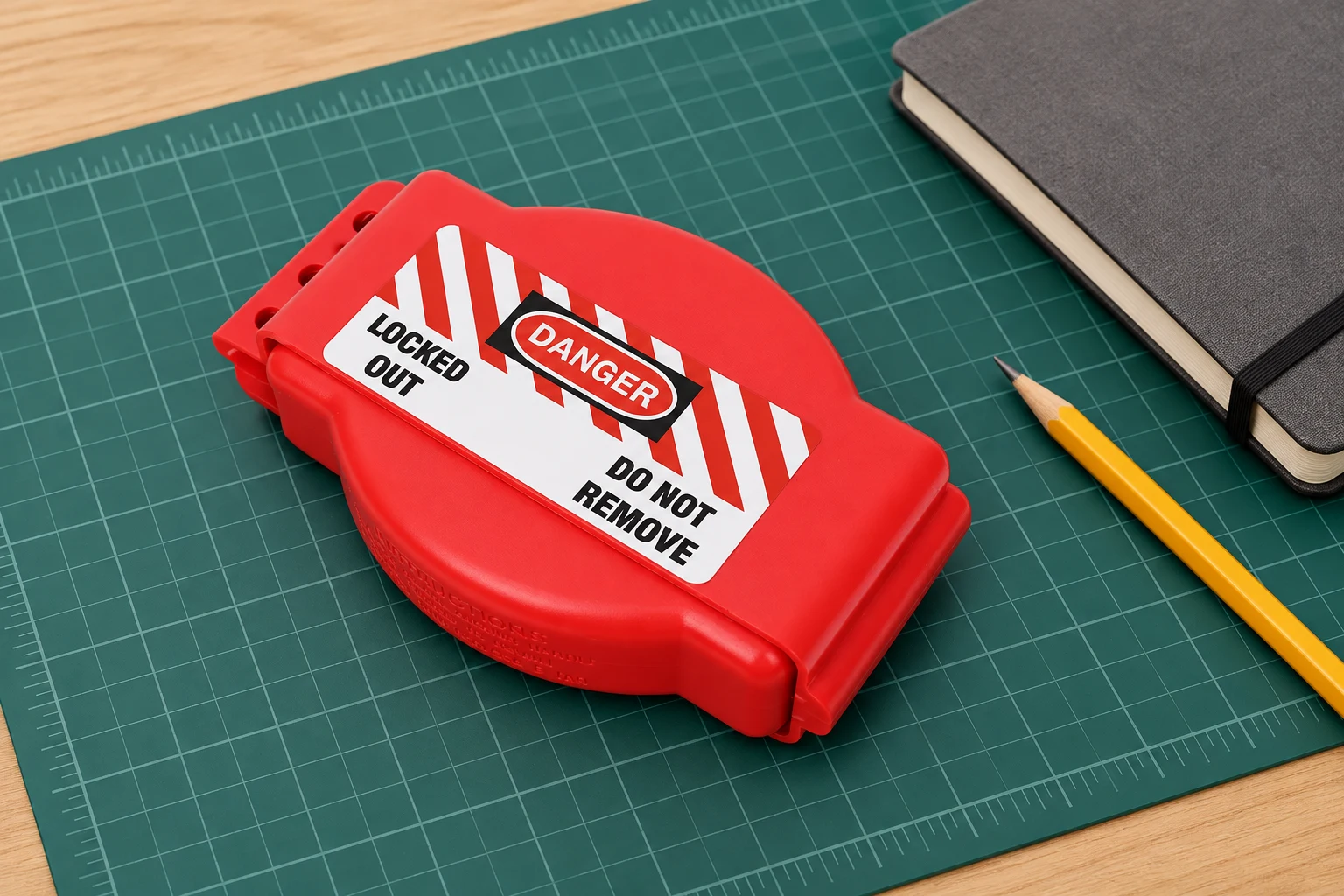
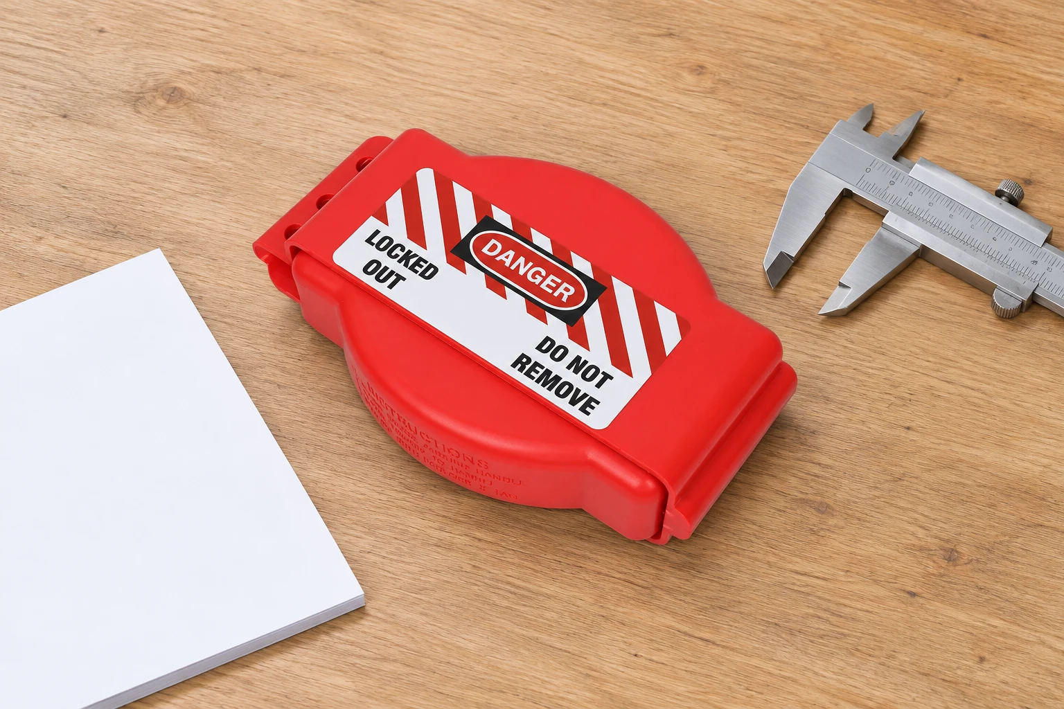
The QVAND gate-valve lockout product provides the real product reference for this article’s illustrations. The pictures preserve the photographed product structure; they do not show a validated rising-stem installation. Obtain written model-specific suitability and a safe sample trial rather than assuming the pictured cover supports every stem geometry.
The CCOHS lockout overview helps place this purchasing work within a documented energy-control program. Combine the fit record with the site’s approved procedure and keep the accepted specification for repeat orders.
Watch: understand where the fit check belongs
Workplace Safety & Prevention Services introduces hazardous energy and lockout in the educational video below. It helps explain why matching the hardware, isolating the system and verifying the safe condition are distinct parts of preparation. It does not demonstrate a rising-stem installation for the pictured model.
Watch the WSPS lockout education video on YouTube.
Frequently asked questions
Is handwheel diameter enough to select a rising-stem valve lockout?
No. Also check wheel depth, hub geometry, stem diameter and projection, installation access and the complete padlock arrangement in the specified safe position.
Can I cut a hole in a cover for the valve stem?
Only perform a manufacturer-defined adjustment explicitly authorized for the exact model and supplied version. Do not create an opening to adapt a device that lacks an approved provision.
Does a locked cover prove a gate valve is leak-tight?
No. The cover provides its intended physical restraint or access restriction. The process-isolation plan must separately address leakage, residual energy and verification.
Should a cover always be unable to rotate?
Not necessarily. Some designs rotate around a captured handwheel while restricting access. Apply the exact model’s instructions and acceptance criteria rather than a universal rotation rule.
Review the referenced QVAND product and send your application details for a model-specific sample discussion.