
A cable lockout device needs a cable route that physically holds the intended energy-isolating device in its safe position. Choosing the longest cable is not enough: the route must resist slipping, the mechanism must retain the cable, and the assembled arrangement must prevent unsafe movement. Before ordering, measure the actual route, check the cable and padlock interfaces, and validate a sample on the identified isolation point. A tight-looking cable does not establish that a machine is safe to service.
This guide focuses on routing and acceptance checks for industrial maintenance teams. For the broader product definition, see what a cable lock is. For available device families, start with QVAND safety cable lockout devices, then confirm the current model instructions and application suitability.
Start with the isolation point, then design the cable route
Identify the equipment, the maintenance task, and every energy source that could expose the worker. Locate the component that actually interrupts or blocks that energy. A cable around a nearby guard or a convenient pipe is not useful merely because it is difficult to remove. It must restrain the intended isolating component through a suitable, approved arrangement.
For example, a handwheel presents several possible paths through its spokes and nearby fixed structure. Those paths do not all produce the same restraint. A loop that can slide toward the center, lift off an attachment, or move with the handwheel can leave operating travel available. The route review should identify exactly what remains fixed and what would have to move to defeat the restraint.
The legal starting point for covered US general-industry servicing is OSHA 29 CFR 1910.147. Its application sequence includes isolating the equipment, applying the lockout, controlling stored energy and verifying isolation. The routing checks below are practical selection tools; they are not additional numerical limits published by OSHA.
Measure the full route rather than the straight-line distance
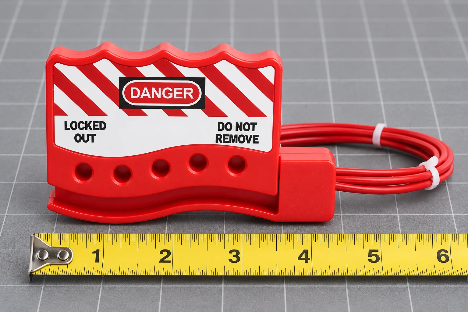
Measure along the intended path through the isolator, around any approved fixed anchor, and back through the locking body. Include bends and the insertion or engagement required by that model. The distance between two points on a drawing is usually shorter than the cable path between them. Use a representative safe mock-up or equipment already placed in a safe condition by authorized personnel.
A useful planning expression is required usable cable length = measured routing path + model-specific engagement allowance + handling allowance. Keep all terms in the same unit. This is a purchasing calculation, not proof of restraint. The model instructions determine which part of the supplied cable is usable and what engagement is necessary; do not invent an allowance when that information is missing.
As a hypothetical example, a measured path of 1.20 m, a supplier-confirmed engagement allowance of 0.15 m, and a handling allowance of 0.10 m produce a planning requirement of 1.45 m. These values illustrate the arithmetic only. They do not describe a QVAND model or establish a universal safe minimum. Check whether a supplier’s nominal length includes a fixed end or unusable section before comparing it with this result.
Longer is not automatically better. Excess cable can obstruct a walkway, catch on equipment, hide identification or complicate tightening. Ask how the unused tail should be managed without changing the approved locking arrangement. Never cut, splice, knot or substitute cable unless the device manufacturer expressly permits that configuration.
Check slack by its effect on movement
A universal acceptable slack value cannot be given for every valve, handle and routing geometry. A small movement can matter on one isolator while a different mechanism has a different travel relationship. The acceptance question is whether the complete installed arrangement holds the isolating device in the required safe position under the site-approved check.
During a controlled fit assessment, follow the manufacturer’s instructions to take up slack and engage the body. Check whether the cable can migrate, whether the body can rotate into a less restrictive position, and whether a loop can be lifted clear without opening the padlock. If the route permits bypass, adding another turn without assessing the new path is not a reliable correction.
Do not test the arrangement by energizing hazardous equipment or pulling harder than the manufacturer allows. A physical fit assessment and a verification of the machine’s energy condition are separate activities. Qualified or authorized personnel must choose the verification method that suits the actual hazards, equipment and local rules.
Use a documented route-acceptance table
The following table is a practical purchasing and field-review aid. Its basis is the requirement to hold the isolator in the safe position, together with the device instructions and the equipment-specific procedure. It does not claim a prescribed cable diameter, pulling force or maximum clearance.
| Check | Evidence to record | Reason to reject or redesign |
|---|---|---|
| Isolation identity | Equipment ID, isolator ID and required safe position | The cable secures an operating control or unrelated structure |
| Route geometry | Photograph showing the full path and fixed anchor | The loop can slip off, migrate or move with the isolator |
| Usable cable length | Measured path and confirmed engagement requirement | Available cable cannot complete the approved route |
| Cable compatibility | Exact device model and manufacturer-approved cable | A substitute cable has unknown retention or environmental suitability |
| Body retention | Closure and retention checks specified in the instructions | The cable withdraws or the mechanism fails to engage |
| Personal padlock fit | Actual shackle fit with the body fully engaged | The padlock appears closed while the device can still open |
| Surrounding access | Clearance for tags, access routes and adjacent equipment | The tail or body creates an obstruction or prevents required access |
Match the cable, body and padlock as one assembly
Do not select cable diameter independently of the locking body. A cable that fits through an opening may still be incompatible with the retention mechanism. Similarly, a shackle may enter a lock hole yet fail to prevent the body’s release because of its diameter, available clearance or the closure position.
Ask for a sample of the actual model and use the personal padlock family intended for the job. If several people participate, confirm the approved personal-protection arrangement rather than counting holes alone. Our guide to how a lockout hasp works explains the role of individual locks; the multi-crew lockbox planning checklist covers coordination and key custody.
A coating is not evidence that a steel cable is suitable for electrical contact. Do not assume dielectric performance, chemical resistance, temperature limits or corrosion life from a photograph. Obtain the relevant model data and assess the environment. Keep any routing work outside electrical exposure unless it is performed under the applicable electrical safe-work procedure by appropriately qualified personnel.
Treat multiple isolation points as a procedure decision
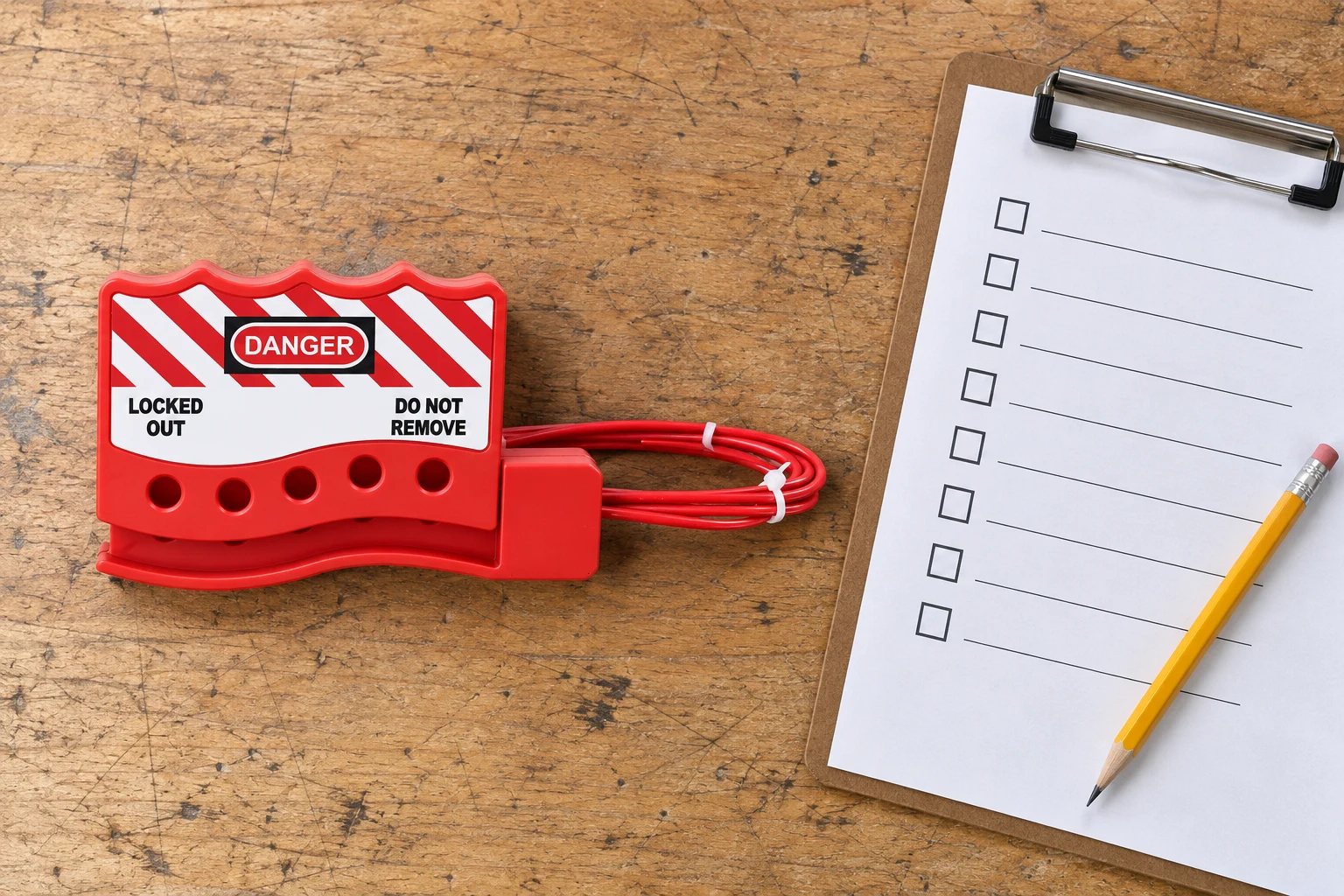
A flexible cable can physically reach more than one point, but reach does not prove that it adequately secures each point. Review every isolator separately. Movement at one point can redistribute slack to another; an anchor acceptable for one component may not be acceptable for the complete route. The procedure must still identify all sources and verification steps.
A single cable also creates a shared physical arrangement. If one point must be released for testing, maintenance sequencing may affect the others. Decide this before the shutdown. Use the site’s formal procedure for temporary removal, testing and reapplication; never improvise a partial release while another worker relies on the arrangement.
The CCOHS lockout guidance provides a useful independent overview of identifying energy, responsibilities and shutdown steps. Its Canadian context should be kept distinct from US requirements. For a valve-focused task, the complementary article on gate-valve lockout application helps connect hardware selection with the operating procedure.
Keep physical restraint separate from energy verification
There are two questions to answer before exposure: does the installed hardware retain the isolator, and has hazardous energy actually been controlled? Neither answer can be inferred from the other. A retained handwheel does not establish an empty pipe, and a stopped motor does not establish absence of electrical voltage.
The task may involve trapped pressure, gravity, hot material, moving components or energy that can reaccumulate. The equipment-specific procedure must identify the necessary release, restraint or continued verification. A cable cannot substitute for those steps. Avoid describing the resulting equipment as universally at “zero energy” if the procedure instead requires a defined safe restraint of residual energy.
The NIOSH hazardous-energy resource guide is useful when developing documented source inventories and procedures. Apply its program resources to the real machine rather than treating a generic checklist as a ready-to-use isolation instruction.
Inspect and record the arrangement before repeat use
Look for damaged or separated strands, cuts or deterioration in the coating, corrosion, a distorted body and irregular retention. Follow the manufacturer’s rejection criteria. Remove questionable hardware from service through the site’s process; tape over damaged cable or an improvised replacement clamp is not an acceptable repair plan.
Keep a route photograph that shows the isolator identity, anchor, cable body, padlock interface and final path. Record the device model, padlock family and reviewer. Reassess when a valve, guard, actuator, access platform or procedure changes. A photograph supports repeatability but does not remove the need to inspect the actual arrangement each time.
What to send with a cable-lockout inquiry
Send QVAND the equipment and isolator identifiers, photographs from several angles, measured route length, available openings, intended padlock details and environmental conditions. State whether a single person or a group will use the arrangement and whether multiple points are involved. Ask for the model instructions and a sample-validation plan before committing to a bulk order.
Request confirmation of the usable cable length, approved cable type, engagement method and relevant limitations. Separate supplier confirmation of product dimensions from the employer’s responsibility to approve the isolation procedure. This produces a clearer purchase specification and avoids assuming that an adjustable device fits every application.
Watch: put the hardware check in the full lockout sequence
Workplace Safety & Prevention Services explains hazardous energy and the lockout sequence in the educational video below. It supports the distinction between stopping, isolating and verifying; it is not an installation tutorial for a particular cable model.
Watch the WSPS lockout education video on YouTube.
Frequently asked questions
How tight should a cable lockout be?
Follow the device instructions and validate the route so the isolator remains in its required safe position. There is no single slack measurement that is safe for every isolator and cable geometry.
Can one cable secure several valves?
Only where the approved device instructions and equipment-specific procedure support the arrangement. Each valve must remain secured, and the assessment must consider slack transfer, verification and any partial-release requirements.
Does plastic-coated steel cable provide electrical insulation?
Do not assume electrical insulation from a plastic coating. Use only verified model-specific ratings and apply the electrical safe-work procedure relevant to the task.
What if the cable fits but the handle still moves?
Reject the arrangement until an authorized review establishes an effective route or selects suitable alternative hardware. A padlock that closes does not by itself demonstrate effective isolation.
Review the referenced QVAND product and send your application details for a model-specific sample discussion.