
A push button lockout cover restricts access to an operating control; it does not turn that control into an energy-isolating device. Before buying a cover for maintenance, identify what the underlying switch actually does. A stop button, selector switch or emergency-stop control normally sends a command through a control circuit. Servicing that exposes workers to hazardous energy requires the applicable equipment-specific isolation procedure, including suitable isolation points and verification. A cover may have a supplementary role, but its presence is not evidence that the machine is de-energized.
This guide helps buyers distinguish control covers from isolation hardware and prepare a useful fit specification. Review QVAND electrical switch lockout products by their actual application and instructions. Product names such as “switch lockout” describe a broad category and cannot establish the function of the installed switch.
First identify the device behind the cover
Start with a drawing review and a safe equipment survey by personnel who understand the circuit. Record the machine identifier, control label and component function. A red mushroom head is a recognizable operator interface, but its color and shape do not establish where hazardous energy is disconnected. The same is true of a selector marked OFF.
Ask a precise question: does operating this component physically interrupt or block the energy source, or does it ask another component to stop? A command can leave supply power present at a motor starter, drive or cabinet. Additional energy sources may remain available even when the machine is stationary.
OSHA 29 CFR 1910.147 distinguishes energy-isolating devices from push buttons, selector switches and other control-circuit devices. The distinction concerns function, not whether an accessory can accept a padlock. This article addresses ordinary hardware selection; it does not establish eligibility for an exception, alternative protective measure or variance.
Compare control covers and isolation hardware
Use the following functional comparison before discussing mounting dimensions. The descriptions are purchasing distinctions based on the component’s role. They are not claims that every product in a category is suitable for every machine.
| Component or accessory | What it can do | What must be established separately |
|---|---|---|
| Push-button cover | Restrict physical access to a specified button when installed as intended | Where hazardous energy is isolated and how isolation is verified |
| Selector-switch cover | Restrict access or movement within the supported control geometry | Whether the underlying device is an operating control or an actual isolator |
| Emergency-stop cover | Provide the particular access-control function stated in its instructions | Effects on emergency accessibility, reset and the machine risk assessment |
| Disconnect lockout | Retain a compatible disconnect in its approved safe position | Correct circuit identification, all other sources and verification |
| Circuit-breaker lockout | Retain a compatible breaker handle using an approved arrangement | Breaker identity, model fit, stored energy and the electrical work procedure |
For the broader selection framework, read the industrial lockout-device guide. If the task calls for isolation at a breaker, use the circuit-breaker lockout range and validate the actual breaker. Do not choose a button cover simply because access to the control panel is easier than access to the disconnect.
Why a stopped machine may remain hazardous
A stop command and an energy disconnection are different events. The machine may stop while conductors remain energized, compressed air remains connected, a raised component remains supported by stored pressure, or a drive retains electrical charge. Some machines can receive commands from another station or an automated sequence.
The purpose of the isolation review is to find those paths before anyone enters the danger zone. Do not use a control-cover fit test as a test of the whole safety system. Similarly, do not infer safety from an indicator lamp being dark or a display reporting a stopped condition.
For work on or near exposed electrical parts, OSHA 1910.333 addresses electrical safe-work practices and does not permit control-circuit devices to be the sole means of de-energizing circuits or equipment. The applicable procedure and qualified personnel must address disconnection and electrical verification. A mechanical cover provides no electrical test result.
Define the cover’s supplementary purpose
Write down why a cover is needed after identifying the actual isolation method. Possible purposes include preventing access to a particular operating control during a controlled condition or preventing an unauthorized change to a selected position where the model is designed for that use. The site must approve the specific purpose and its place in the procedure.
Separate “restrict access” from “retain position.” Some covers enclose a button while others constrain a lever or selector. A transparent enclosure can improve visibility without preventing every possible movement. Review the instructions rather than assuming that a closed lid immobilizes the control underneath it.
Record which device provides personal protection, which accessory is supplementary, and who may remove each device. If workers cannot explain that difference during a walkthrough, clarify the procedure before issuing the hardware. The phrase “locked out at the panel” is too ambiguous when several different controls and isolators exist.
Do not compromise access to an emergency stop
A cover near an emergency control needs particular care. During normal operation, workers may need rapid access to stop a hazardous motion. A cover that obstructs access, obscures the control, or changes the required operating action can create a separate problem even if it fits neatly on the panel.
Have the responsible machine-safety personnel assess the exact operating state and intended use. Distinguish a temporary maintenance arrangement from a permanently installed guard or access-control accessory. Never assume that enclosing an emergency stop is an acceptable routine way to prevent nuisance operation.
Review the equipment manufacturer’s instructions, the machine risk assessment and applicable local requirements. Do not change emergency-stop availability, reset behavior or mounting merely to accommodate a chosen product. If safe access and the cover’s intended use cannot both be maintained, choose a different arrangement through the site’s engineering review.
Measure the complete operating envelope
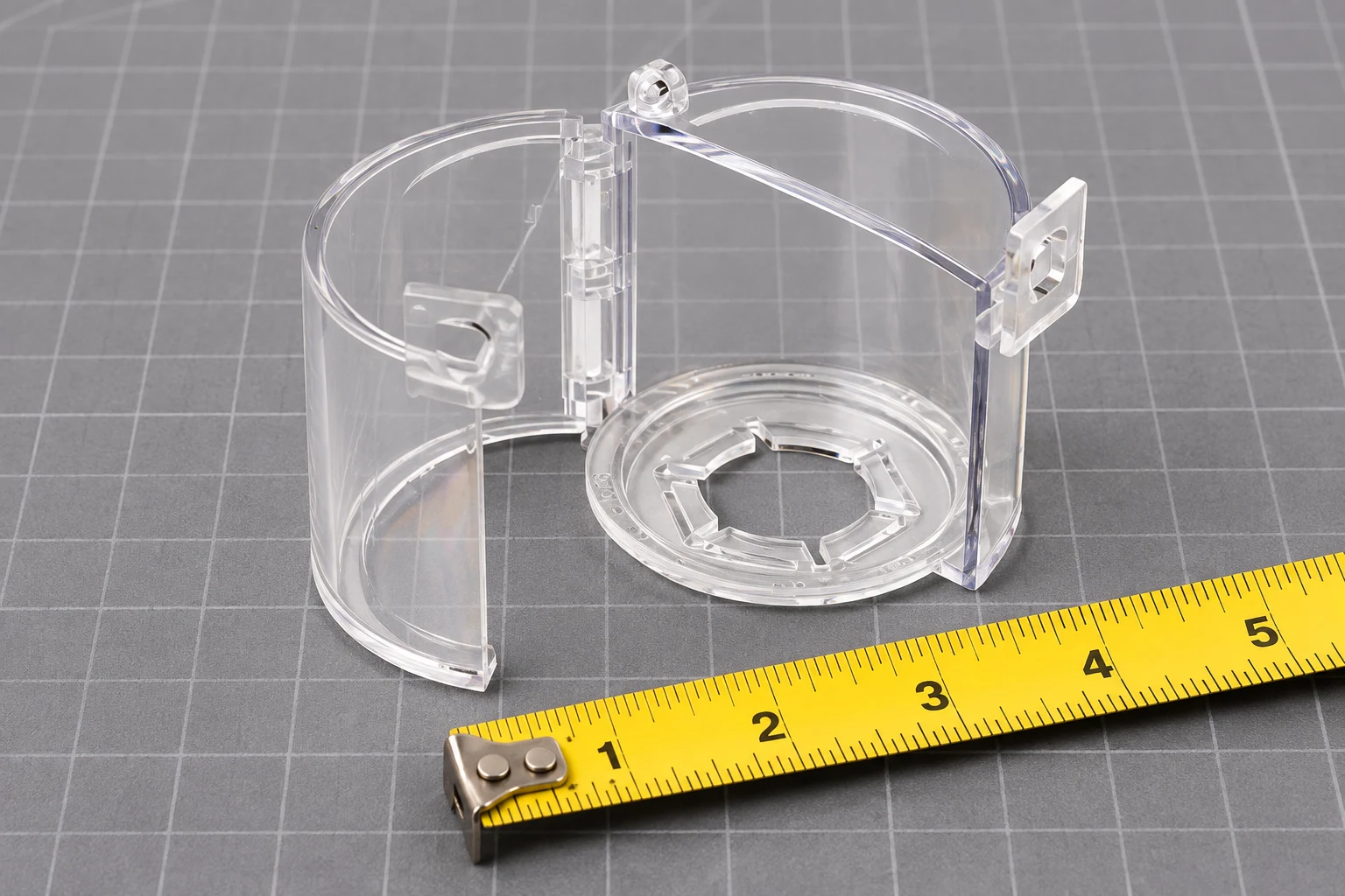
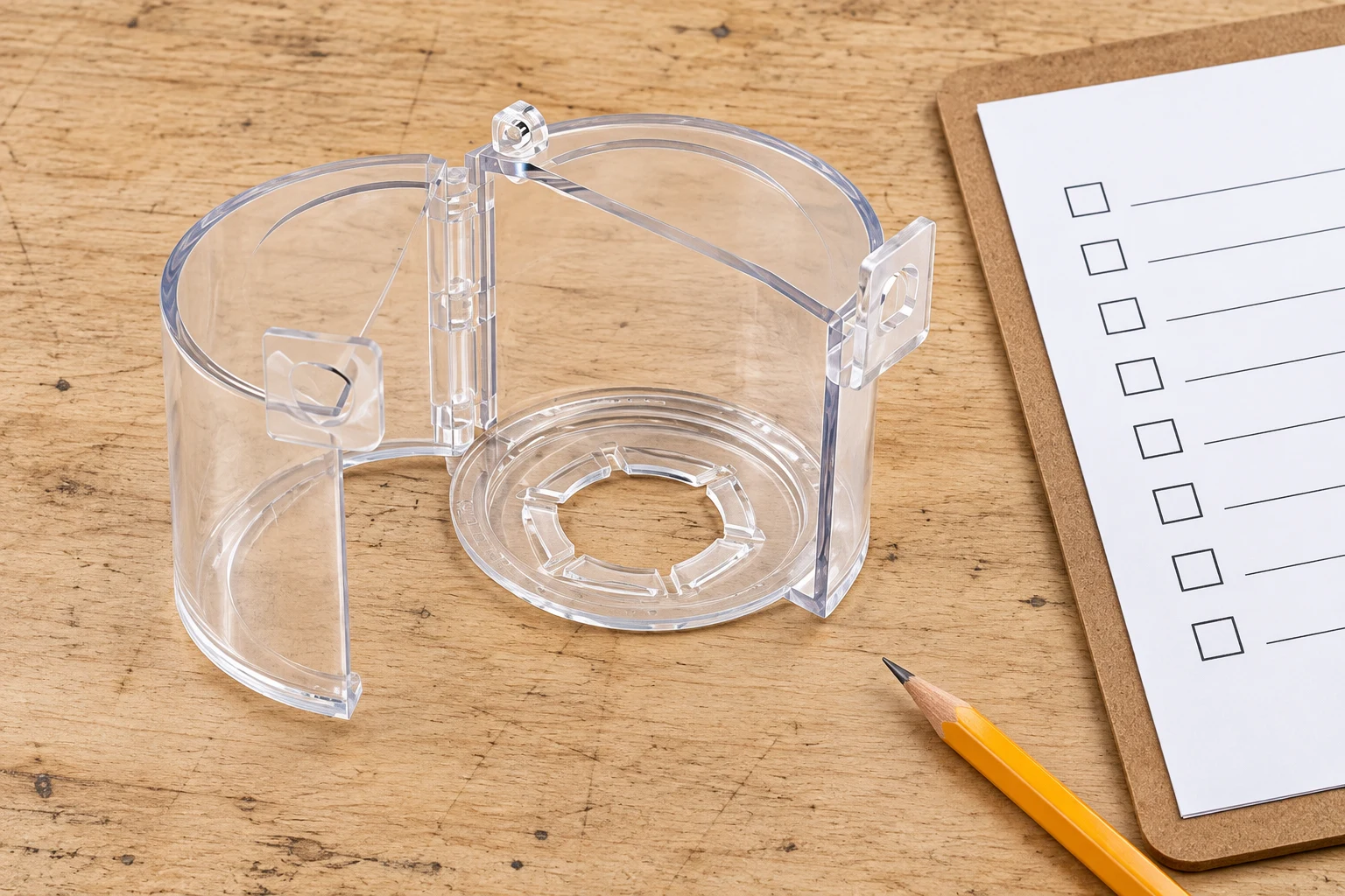
A panel’s nominal mounting-hole size is only one dimension. Measure the button head, bezel or collar, protrusion from the panel and the movement required for its designed action. A mushroom control, a key selector and a flush push button can need very different internal clearance even when their panel mounting sizes are similar.
Record the base footprint, distance to adjacent controls, available flat mounting surface and clearance for opening the lid. Include space for the actual padlock and identification tag. Photograph the control from the front and side with a scale where this can be done safely. Do not open an energized enclosure to collect purchasing measurements.
Ask the supplier to confirm mounting compatibility and approved installation method. Adhesive, screw-fixed and removable arrangements have different instructions and preparation requirements. Do not drill a panel, modify an enclosure seal or apply an unapproved adhesive as an improvised fix. Installation changes require appropriate authorization and safe conditions.
Use a sample acceptance checklist before bulk ordering
Evaluate a sample on a representative safe panel or controlled mock-up. Use the exact control and padlock family intended for service. A catalogue image cannot reveal every collision between the lid, bezel, shackle and neighboring equipment.
- Confirm the device identity and record whether it is a control or an isolator.
- Compare the product instructions with the documented supplementary purpose.
- Check mounting security and closure without forcing the base or lid.
- Check the required restraint or access restriction with the actual padlock installed.
- Check visibility, tag attachment, adjacent controls and necessary emergency access.
- Record the result, limitations, responsible reviewer and permitted equipment applications.
This is a hardware acceptance exercise, not permission to service the machine. The maintenance authorization still depends on the complete energy-control procedure. If the sample fails, document the failed condition rather than purchasing a different size on guesswork.
Connect the control label to the written procedure
Use identifiers that distinguish the stop control from the energy-isolating disconnect. For example, a procedure can identify the panel control used for orderly shutdown separately from the disconnect used for electrical isolation. The example describes documentation structure, not a ready-made shutdown sequence.
For a deeper discussion of that mapping, read mapping circuit breakers to written LOTO procedures. When building the task inventory, use the complementary equipment-specific products and signs checklist. These resources cover identification and planning; the present article focuses on control covers and their limitations.
Keep the procedure current when controls, panels, actuators or operating modes change. Replacement hardware may look similar while its dimensions or circuit function differ. Revalidate the application after relevant changes instead of transferring approval solely because the old cover can still be attached.
What to include in a switch-cover inquiry
Send QVAND the control type, intended purpose, photographs, head and bezel dimensions, protrusion, available panel area, neighboring clearances and padlock details. State the environment and the proposed mounting method. Ask for exact dimensions, installation instructions and any use restrictions for the candidate model.
Also state which separately identified devices will provide energy isolation during servicing. This helps prevent a quotation from being mistaken for approval of the machine’s safety procedure. Avoid vague requests for an “OSHA-approved button lock.” A supplier can confirm product characteristics; the employer must determine the appropriate application and compliance obligations.
The NIOSH hazardous-energy control resource guide can help structure the supporting program, including documented procedures, training and inspections. Use it to improve the site’s process rather than claiming that a purchased cover makes the entire installation compliant.
Watch: understand the complete energy-control sequence
This educational video from Workplace Safety & Prevention Services introduces hazardous energy and lockout. Use it to reinforce why a visible stopped condition is only part of preparing equipment for safe maintenance. It does not approve a particular cover or substitute for site-specific training.
Watch the WSPS lockout education video on YouTube.
Frequently asked questions
Is a push button an energy-isolating device?
Under OSHA 1910.147, push buttons and other control-circuit devices are not energy-isolating devices. Identify and secure the actual isolating components required by the equipment-specific procedure.
Can a locked emergency-stop button replace disconnect lockout?
A cover on an emergency-stop control does not itself provide energy isolation. Use the applicable isolation procedure and have the cover’s effect on emergency access reviewed separately.
Does an OFF label prove that a switch disconnects power?
No. The component’s actual circuit function determines whether it isolates energy. Have suitable personnel confirm that function rather than relying on the label or appearance.
What measurements should I send to a supplier?
Provide the control head and bezel dimensions, protrusion, operating movement, base area, adjacent clearances, mounting conditions and actual padlock details, together with photographs and the intended use.
Review the referenced QVAND product and send your application details for a model-specific sample discussion.